In order to save cost, our team decided to use the basic 6’ by 6’ by 6.5’ frame developed for our sketch model and modify it to create a final demonstration prototype. The sketch model was rudimentary in a number of dimensions, and our initial modifications focused on five main areas:
The sketch model we designed had the simplest possible control mechanism which allowed us to still test the game’s basic mechanics. Namely, the users pulled on lengths of rope guided through eye-hooks to move the truss (x-direction) and trolley (y-direction), and the hook (z-direction) was raised and lowered by a person pulling on a rope which passed through the center of the trolley.
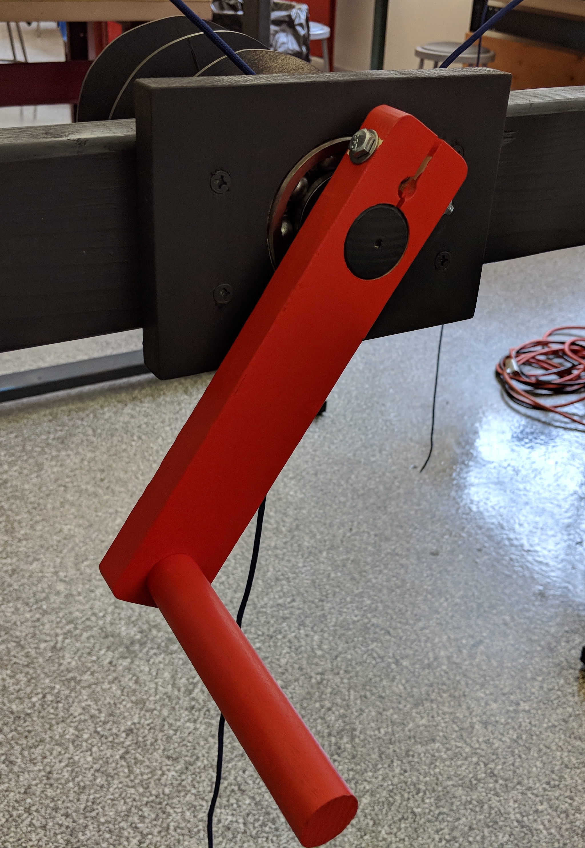
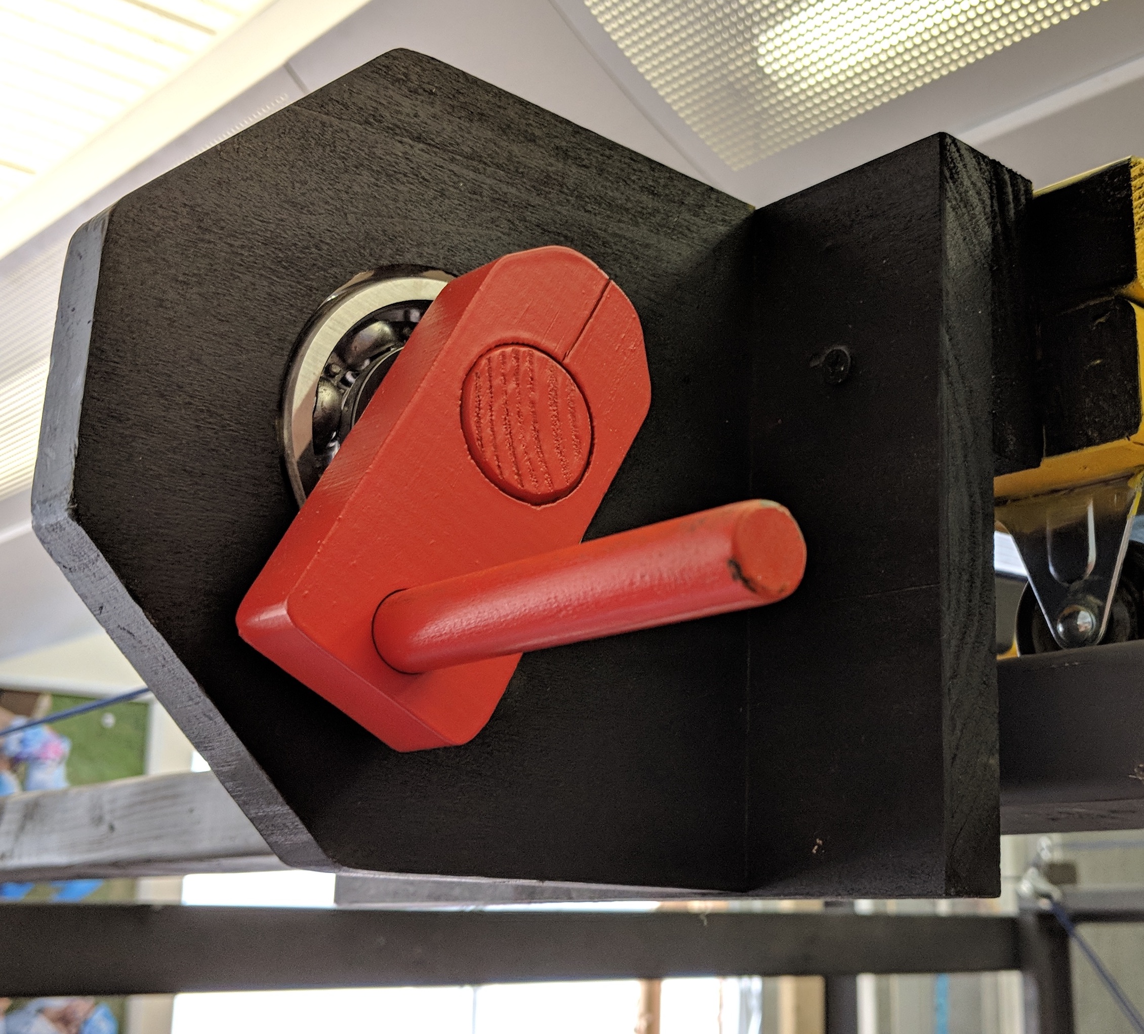
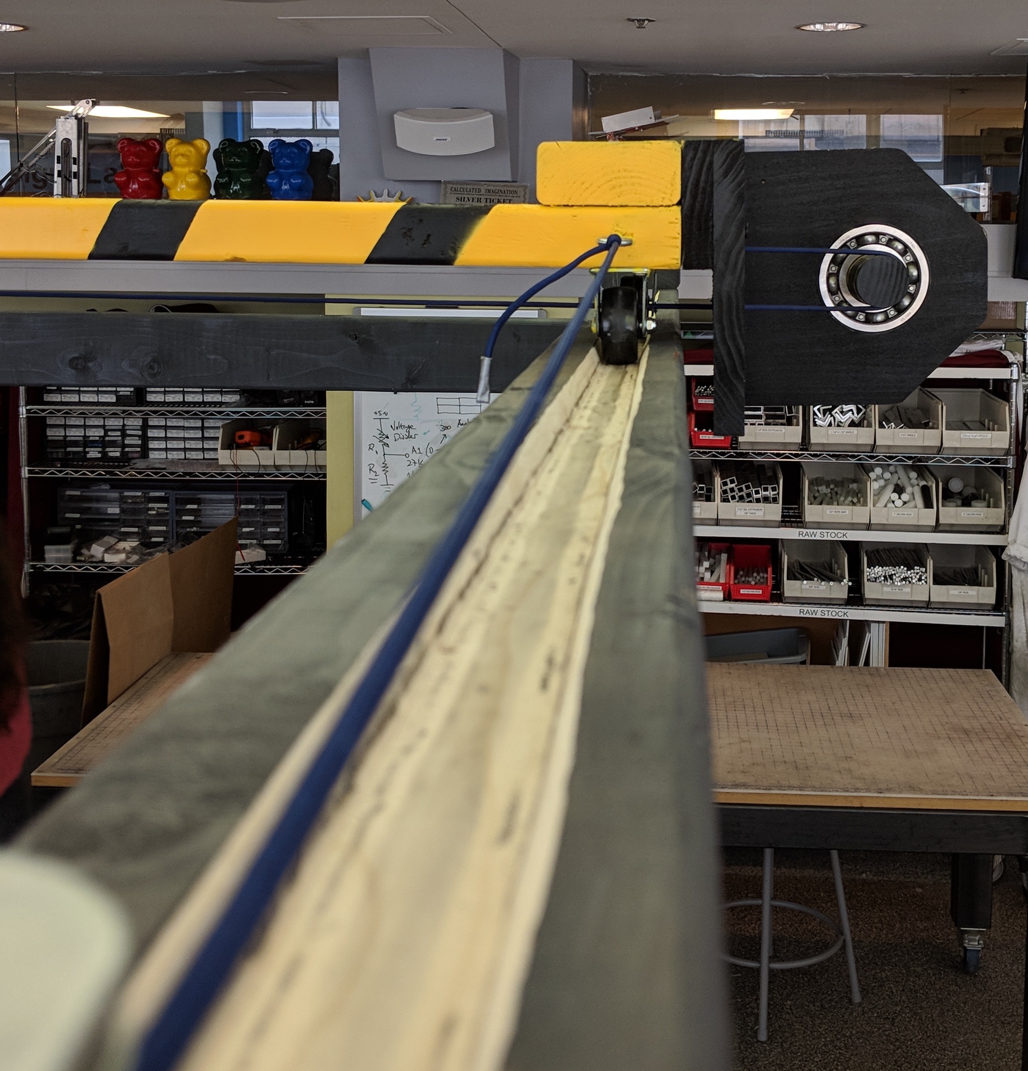
For the final prototype, we wanted to create crank and lever surfaces which would provide a more intuitive and tactile experience. For the truss, this was accomplished by adding a cross-member at the frame’s beltline and mounting a crank / pulley system in which two counter-wound cables pulled the truss in the positive and negative direction as the crank was rotated.
For the trolley, a similar crank was added to the truss itself; a single loop of cable was wound around a crank and opposing pulley to move the trolley along the y-direction. Although this does not fully isolate the y-direction from the x-direction (the user must walk along with the truss as it is moved), this method of implementation had advantages with respect to simplicity, robustness, and ease of setup / teardown.
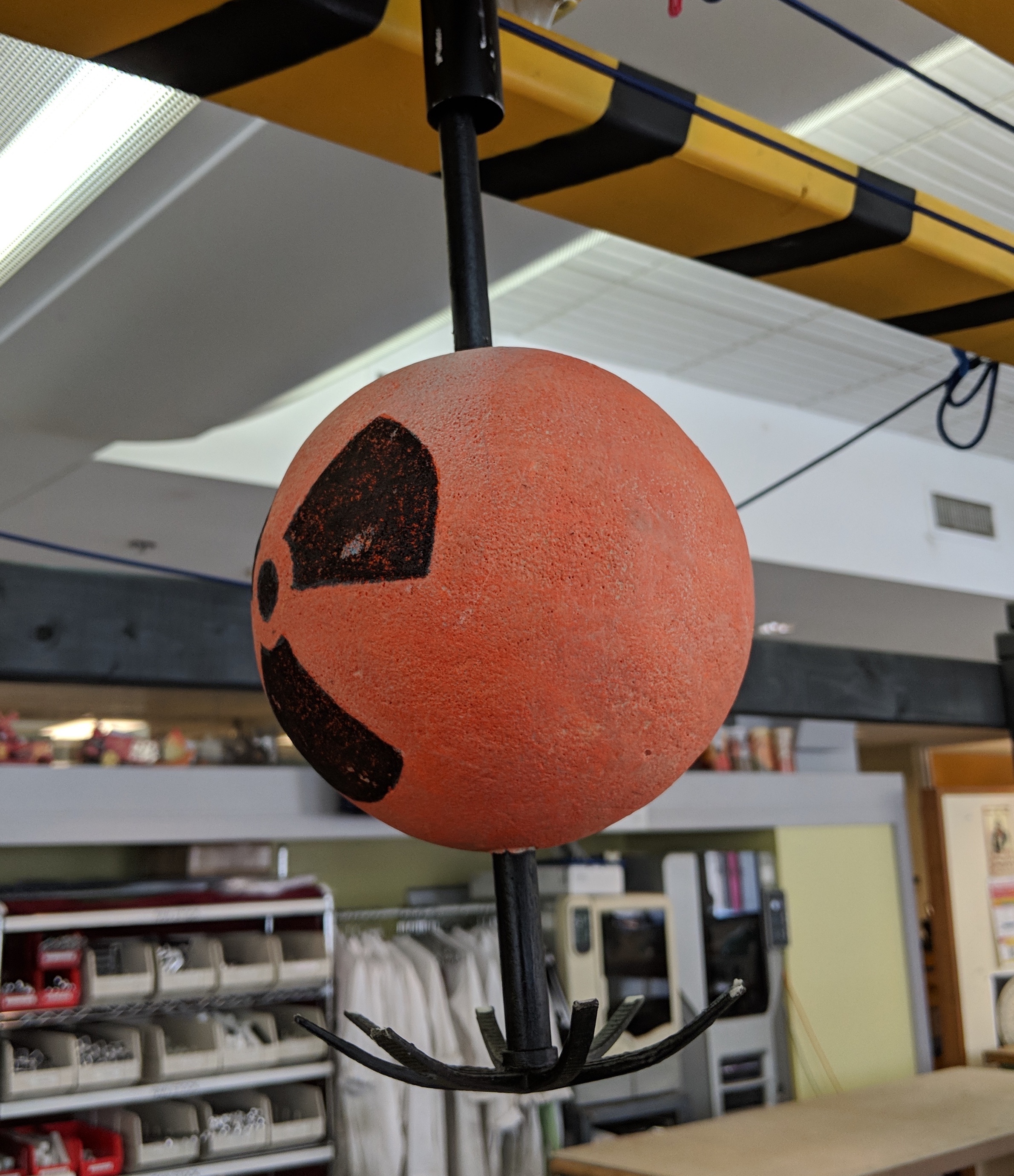
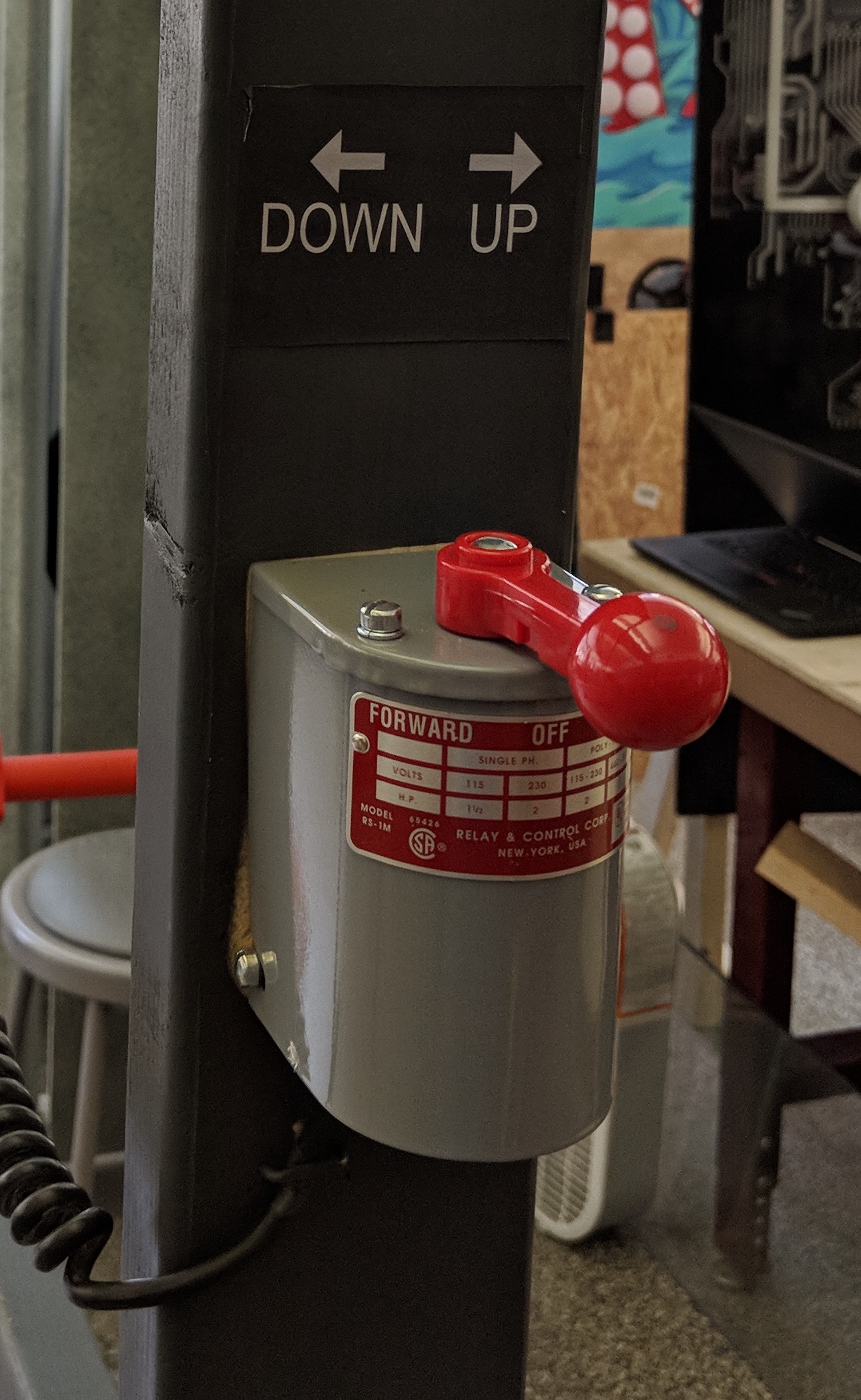
Finally, the hook control was converted to an electric motor. The rationale for this was two-fold: first, it offered the users an alternative type of control surface and methodology. Second, it allowed us to more easily isolate the actuation of the hook from the other two control directions; this is expounded further later on.
One of the primary disadvantages of the sketch model control implementation was that the z-direction hook movement was dependent upon the crane’s movement in the x and y directions. If the z-direction rope was held still while the x and y position were changed, the z-position would change as a consequence of the changing distance from the hole in the trolley to the z-direction pull point.
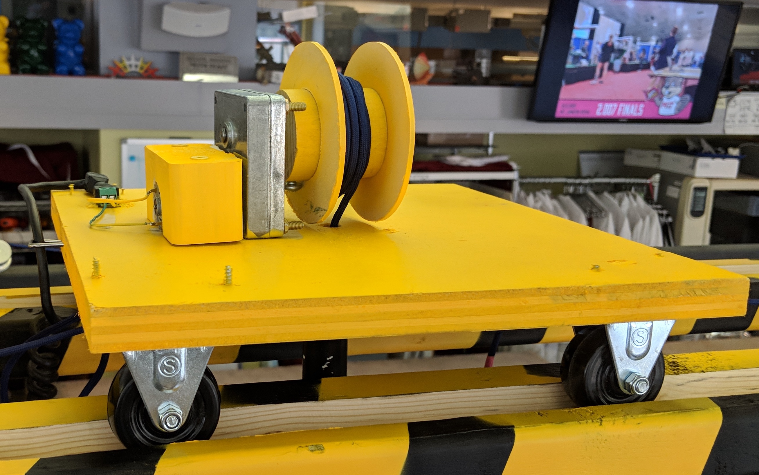
As discussed on the previous page, this was resolved by using an electric motor for hook actuation in the final prototype. A small (10 in.-lbs. torque at X RPM) DC motor was installed on the trolley itself and fitted with a small spool. This motor was in turn powered by a self-tensioning electric cable which prevented an excessive length of power cord from hanging into the play area of the control rod game.
The option to offer a hi/lo speed switch (by reducing the supply voltage) was considered, but the single speed of the motor used provided an appropriate balance of gameplay speed and difficulty.
One of the major challenges encountered during the sketch model phase of control rod crisis was ‘bite’ – when the truss bound in its track because of slight rotation of the truss as it was being pulled.
As discussed on the previous page, this was resolved by using an electric motor for hook actuation in the final prototype. A small (10 in.-lbs. torque at X RPM) DC motor was installed on the trolley itself and fitted with a small spool. This motor was in turn powered by a self-tensioning electric cable which prevented an excessive length of power cord from hanging into the play area of the control rod game.
The truss bite was ameliorated in two ways. First, the channels in which the wheels of the truss traveled were beveled out. The consequence of the bevel was such that the truss no longer firmly bound in the track and was free to ride up the walls of the channel some small amount. Consequently, the truss could rotate to a greater degree without completely preventing the truss from being pulled.
Second, in the pull direction where bite was more evident, the single pull point was split such that the truss was pulled from both end points. This modification made it such that, if one side of the truss began to lag, it would experience a stronger pulling force as the tension in that cable increased. This provided a self-correcting mechanism for truss bite.
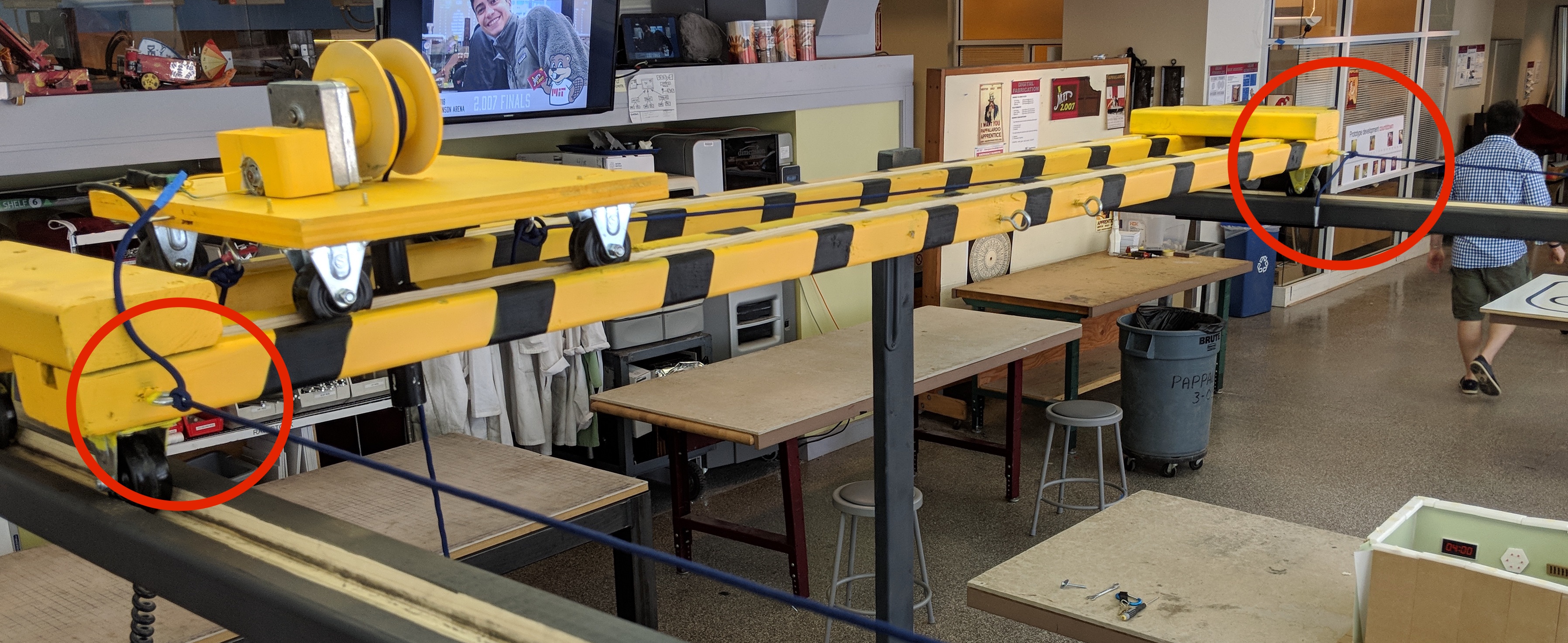
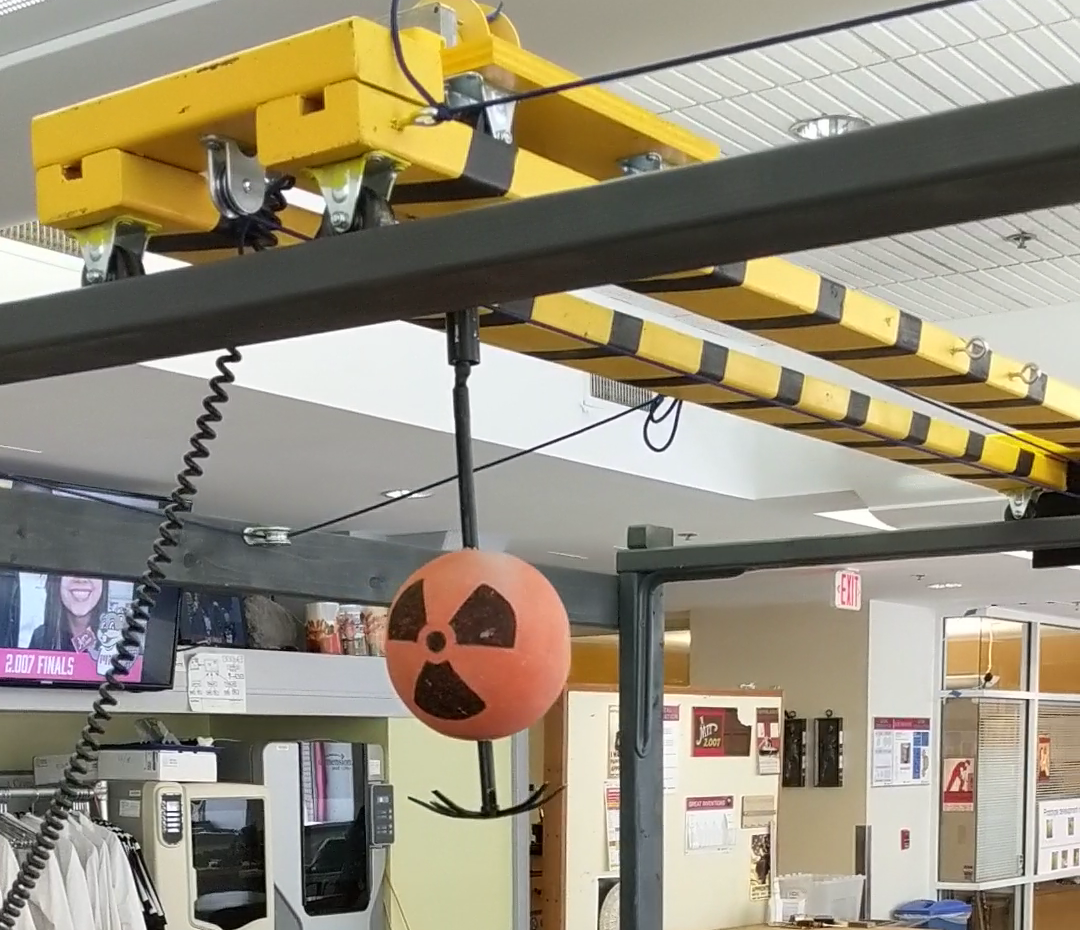
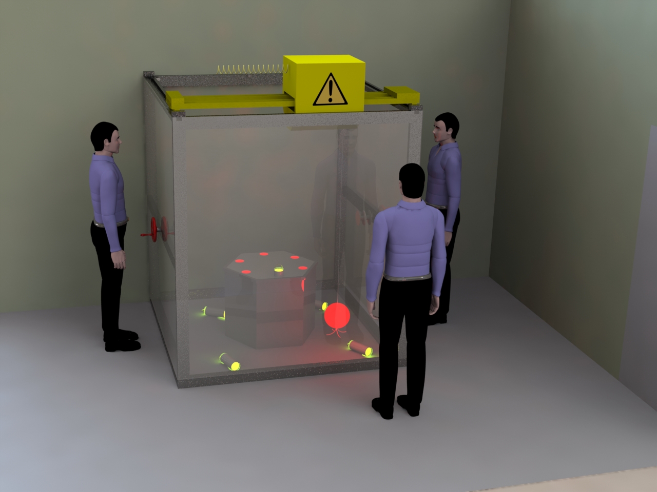
The form characteristics of the final prototype model were more carefully considered than they were in the sketch model. Specifically, color was used to improve the human use factors and visual appeal of the prototype.
The various structural components of the crane were painted matte grey. This color choice had two intents. The first was to provide some plausible feel of an industrial metal frame, at least upon cursory examination. The second was to mute the color of the structure so that it would not distract from the components with which the users were to interact with.
Each of the control components – the cranks for the truss and trolley and the lever for the hook control – were all colored a bright red. The objective of this color choice was to quickly draw the user’s attention to the components of the game with which they would be interacting.
Finally, the truss and trolley were painted with a ‘caution’ yellow and black scheme. Once again, this color scheme was pursued to provide a combination of a realistic feel and to inform users that those pieces of the crane mechanism could be moved.
The final difference between the sketch model and the final prototype was the integration of the hook to the crane. The final hook was assembled using a 3D printer and heat formed to achieve a shape which facilitated hooking and unhooking the control rods. This hook was attached to a relatively long wooden dowel which was then tied to the hook’s rope. The wooden dowel raised the center of rotation about the hook, preventing it from rotating and allowing the rod to slip off after being hooked.